Author: Nick Gammon
Date written: March 2022
The firmware on the EEPROM supports connecting to SPI devices. This is implemented in software and does not require any additional hardware.
Demonstration videos on Vimeo of:
See:
SPI is commonly used in many devices such as port-expanders like the MCP23S17, micro SD cards, 7-segment and 8x8 matrix displays using the MAX7219 chip, and many others.
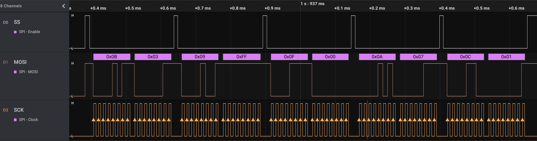
Screen capture of the logic analyzer while sending data to the MAX7219 chip (open image in new tab for more detail).
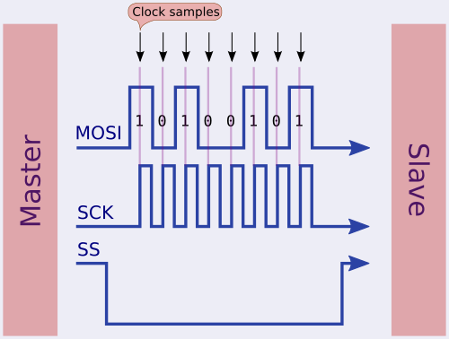
SPI uses four signal lines (plus power and ground) as follows:
Three of them (SS, MOSI, SCK) are outputs from the master, and one is an input from the slave. In this implementation the breadboard computer is considered to be the master.
Note that on some devices the signals are labelled slightly differently:

Some devices, like the MAX7219 chips used on LED displays do not output anything, so MISO can be omitted, like this:
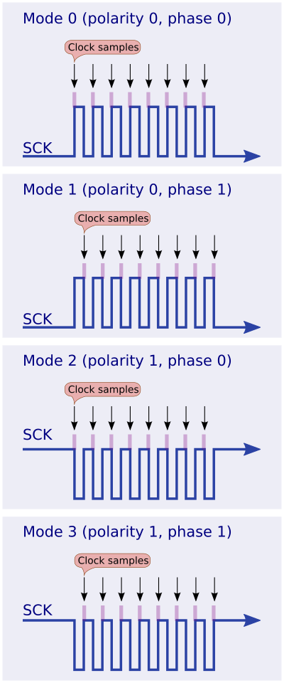
There are four clock and sampling modes used by SPI, where mode 0 is the most common I have seen:
I have used VIA ports PB0, PB1, PB2 and PB3. On Ben’s original board they were connected to the LCD display, however since I rewrote the LCD code to use only a 4-bit interface those pins are now free. So, first disconnect those ports from the LCD. That is VIA pins 10, 11, 12 and 13.
The code expects you to connect:
The firmware on the EEPROM has five exposed functions (subroutines) you can call, plus a pointer to a character-code table:
This initialises the VIA chip ready for SPI communications. You should load the mode (described above) into the A register before calling this. It sets SS, MOSI, and SCK to be outputs and MISO to be an input. It also sets the clock (SCK) and slave select (SS) to the correct levels. The clock is normally low in mode 0, and slave select is normally high.
Example:
   lda #0   ; mode zero
jsr spi_initThis transfers one byte from the master to the slave, and simultaneously receives one byte from the slave. The byte to be sent is placed in the A register. After the transfer the byte which has been received is in the A register. The X and Y registers are preserved.
Example:
   lda #42
   jsr spi_transfer   ; send 42 to the device
sta foo ; any incoming data from the device is now in AThis sets SS (slave/chip select) to low, which is the normal way of telling the slave that you are about to communicate with it. All registers are preserved.
This sets SS (slave/chip select) to high, which is the normal way of ending a session with the slave. All registers are preserved.
This sends two bytes to the slave. The first byte is in A, and the second byte in X. All registers are preserved.
This functionally is the same as:
spi_send_two_bytes:
  pha
  jsr spi_ss_low    ; SS low
  jsr spi_transfer  ; send first byte
  txa               ; get second byte
  jsr spi_transfer  ; send second byte
  jsr spi_ss_high   ; SS high again
  pla
  rts
This is a useful helper function. Chips often expect you to send a register number first, followed by the value to put into that register.
Example:
  lda #MAX7219_REG_INTENSITY    ; character intensity: range: 0 to 15
  ldx #7                        ; intensity 7
jsr spi_send_two_bytesThis is a 2k chunk of memory in the EEPROM with the character encoding for the CP437 font.
This looks like this:
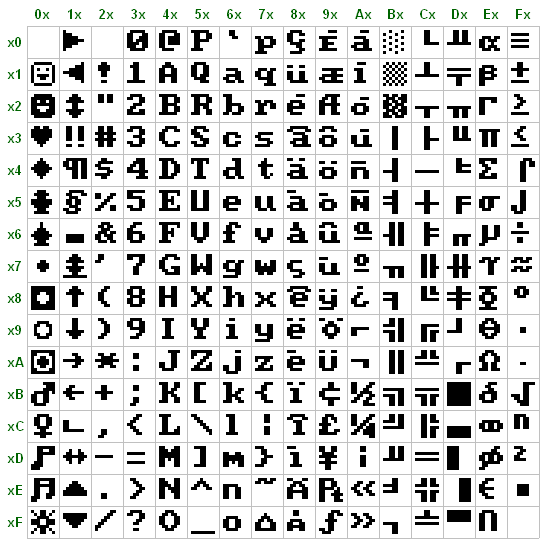
This is very useful if you want to draw characters on a 8x8 dot matrix display, as putting the font data into your code could easily exceed your available RAM for your source.
The example file Driving an 8x8 matrix display shows you to use this font data. Basically each byte that can be displayed (from 0x00 to 0xFF) takes up 8 bytes of font data (one for each line of the display, therefore 8 bytes x 8 bits = 64 pixels).
Although this is a lot of memory devoted to a font you may not use, the EEPROM is there anyway, so it may as well have the font data in it. If you are recompiling the assembler source with your own code, and running out of memory, simply disable the inclusion of the font data. In other words, in gpascal.asm change:
USE_CP437_FONT = 1to:
USE_CP437_FONT = 0Information and images on this site are licensed under the Creative Commons Attribution 3.0 Australia License unless stated otherwise.