
Author: Nick Gammon
Date written: February 2022
Author: Nick Gammon (written in 2022)
The G-Pascal assembler is a 65C02 assembler, entirely resident in the EEPROM, and available immediately after resetting your board. This is intended to let you try small to medium-scale assembler projects, without having to keep removing the EEPROM chip and programming it externally.
The documented WD65C02 instruction set, with all operand modes
Full expression evaluation of operands, with operator precedence, parentheses, bitwise operations and so on.
Relocation of the output to any memory address (ORG directive)
Here is “hello world” in assembler:
      jmp begin   ; skip the message
hello asciiz "Hello, world!"
begin = *
      lda #<hello
      ldx #>hello
      jsr print
rtsUse the Editor to enter your program (type “I” to insert text). Alternatively load it from your PC by using “LOAD”. The Editor is described in a separate page.
Type “A” to assemble it and produce machine code.
If it assembles without errors type “R” to run the code. It will automatically start running at the location of the first byte of emitted machine code. It is probably useful to put a JMP there to go to where you want the code to start executing. Put a RTS at the end of your code to return to the G-Pascal system. Alternatively, JMP RESTART to do a “warm start” if you aren’t sure a RTS will take you back to where you started.
The assembler is intended to be compatible — to a point — with the vasm6502 assembler, in particular when run on your PC like this:
vasm6502_oldstyle MYFILE.asm -wdc02 -esc -Fbin -o MYFILE.bin -L MYFILE.listNote that there is a limit to how much can be implemented in a few kB of EEPROM. Thus source files written in this assembler should compile in vasm, however if you use extra features of vasm (like conditional compiles) then these are not supported. In other words, file written here should be compatible with vasm, not necessarily the other way around.
Vasm is available from http://sun.hasenbraten.de/vasm/
The assembler is line-based, that is each line is treated separately, and is terminated by the newline character (0x0A).
A line may optionally contain of a label, which must be located in column 1 (the first column).
Whitespace (spaces) are ignored, except that a label must start in the first column.
A comment starts with semicolon (“;”) and continues to the end of the line. Lines may consist entirely of comments, or be entirely blank.
Opcodes (eg. LDA) or directives (eq. ORG) are separated from the label, if present, by one or more spaces. If there is no label then the opcode must be at least on column 2 of the line. Opcodes are not case-sensitive.
A test file is here which assembles every opcode/addressing-mode combination. The expected code to be generated is shown in the comments. This should assemble the same under this assembler and vasm.
Operands are separated from the opcode by one or more spaces.
The operand "*" evaluates to the current output code address, eg.
foo =   *       ; foo is assigned to the current address
    bra *+4   ; branch to 4 bytes ahead of this instruction
In the case of opcodes which may or may not use the A register as an operand, the “A” may be omitted. eg.
  LSR    ; logical shift A right
  INC    ; increment A
String operands only apply to the ASC, ASCII, ASCIIZ and STRING directives. In those cases a quoted string of any length (up to 255 characters) may be the operand. In a similar way to the Pascal compiler, strings may start with either single of double quotes, and contain the other type of quote inside. Alternatively you may double the starting quote to include it in the string. eg. ‘Nick’‘s cat’. In other places strings of one to three characters long may be used, and will be treated as numbers. Eg.
lda #'A' ; load A with $41Strings may also contain “escape” sequences of a backslash followed by a letter, as follows:
  \A    bell ($07)
  \B    backspace ($08)
  \E    escape  (0x1B)
  \F    formfeed ($0C)
  \N    newline  (0x0A)
  \R    carriage return (0x0D)
  \T    horizontal tab (0x09)
  \V    vertical tab (0x0B)
  \'    single quote
  \"    double quote
  \\    backslash
  \Xnn  where nn is one or two hex digits (eg. \x0A \X42 \x9 )
The letter following the backslash is not case-dependent. For the \Xnn form, if there is potential confusion if the character following the escape sequence happens to be a hex digit then you should use two digits. Only the first two digits are considered when parsing.
Other operands go through the “expression evaluator” after taking into account indirect addressing which is noticed by the presence of a leading “(” on the line.
The expression evaluator combines values using operators following the following precedence list, as obtained from the vasm documentation:
   1.   + - ! ~ (unary +/- sign, not, complement),  also < (low-byte) > (high byte)
   2.   << >> (shift left, shift right)
   3.   & (bitwise and)
   4.   ^ (bitwise exclusive-or)
   5.   | (bitwise inclusive-or)
   6.   * / % (multiply, divide, modulo)
   7.   + - (plus, minus)
   8.   < > <= >= (less, greater, less or equal, greater or equal)
   9.   == != <> (equality, inequality)
  10.   && (logical and)
  11.   || (logical or)
The high-byte and low-byte operators are unary operators with a high precedence. Depending on their location in the expression they are not considered to be comparison operators. For example :
  lda #>foo           ; load A with the high-order byte of the address of foo
  lda #>(foo + $100)  ; load A with the high-order byte of the address of (foo + $100)
  lda #<foo           ; load A with the low-order byte of the address of foo
There is a operator evaluation test file you can try.
Parentheses may be used to force the order of evaluation of operators.
Labels, if used in expressions, take on the value of the address of that label.
Expressions are evaluated internally to 24 bits of precision, and then truncated to 16 bits at the end of the expression evaluation. This means that operations which might overflow 16 bits may still evaluate correctly. eg. lda # ($8000 << 4) >> 12 would generate a9 80 (that is, lda #$80) because the high-order bit was not lost during the initial shift left (it was still in the range of a 24-bit value).
A quirk of the numeric literal parser means you cannot directly use the numeric literal -8388608 in a program. A workaround it to use $800000 instead as that is the hex equivalent of that value, or to use (-8388607 - 1). This is because the parser allows a number of up to 23 bits (0 to 8388607) and then sets the high-order bit to make it negative if you provided a minus sign.
The following assembler directives are supported:
LIST number
This controls the listing of your code during assembly. It consists of three bits which may be OR’ed together as follows:
For example:
  LIST 1        ; show source
  LIST 1|2      ; show source and generated code (alternatively: LIST 3)
  LIST 1|2|4    ; show source, generated code, and user-defined symbols (alternatively: LIST 7)
  LIST 1|2|4|8  ; show source, generated code, and ALL symbols (alternatively: LIST 15)
  LIST 0        ; stop listing anything
The assembler does two passes, the first to find the address of forward-declared symbols, and the second to output the machine code. The listing is shown during the second pass, unless there is an error, in which case the line in error is shown.
LIST
Same as “LIST 3”.
NOLIST
Same as “LIST 0”.
ASSERT expression
Raises an error “Assertion failed” if expression is zero. This can be used to do compile-time checking. For example, you could check if a block of memory exceeded a certain size. You can also use it to check that the assembler is evaluating expressions correctly, for example:
assert 2 + 2 == 4ASC string
Insert the string into the code, with no terminator.
asc "Hello, world!"ASCII string
Same as ASC.
ASCIIZ string
Insert the string into the code, with a 0x00 (null) terminator.
STRING string
Same as ASCIIZ.
label EQU address
The specified label takes on the address of the evaluated expression.
EEPROM         EQU    $8000
start_message  ASC    "Hi there"
end_message    EQU    *   ; end_message becomes the current output address
message_length EQU    end_message - start_message   ; calculate message length
label = address
Same as EQU.
ORG expression
The output generation is relocated to whatever expression evaluates to, from this point on. If this line had a label the label evaluates to the address before the relocation.
org $5000 ; output code at $5000 onwards nowDFB expression [, expression ]
A byte is emitted to the output, which is the value of the expression. It must evaluate to 0x00 to 0xFF. Multiple bytes may be emitted separated by commas.
dfb $01,$02,$03,$04DFW expression [, expression ]
Two bytes (one word) are emitted to the output, which is the value of the expression. It must evaluate to 0x0000 to 0xFFFF. The bytes are emitted in little-endian order, that is the low-order byte first, followed by the high-order byte. Multiple words may be emitted separated by commas.
dfw $1234,$5678,$ABCDWORD expression [, expression ]
Same as DFW.
BLK expression
The assembler emits expression zeroes. For example:
BLK 10 ; emit 10 zeroes, advancing the output address by 10RESERVE expression
The assembler advances the output address by expression bytes without emitting anything. This could be handy for reserving blocks of memory without overwriting them during the assembly process.
SYM expression
Relocate the symbol table, used during assembly, to the address that expression evaluates to. This must be done before any symbols are created (that is, before any labels). The intention of this is to allow you to make a “safe place” for code which could be shared by the Pascal compiler and the assembler, as described below.
For example:
  SYM $4800     ; symbols are to be placed at $4800 (growing downwards)
  ORG $4800     ; code is to be placed at $4800 (growing updwards)
You will not get an error if you have already created symbols (labels), however once the symbol table has been relocated the library symbols will be reloaded into the new location, and your existing symbols discarded.
In the absence of an ORG directive, the generated code is placed directly after the end of the source code. This is fine for testing out assembly-code ideas.
During assembly the symbol table is placed at the top of RAM and grows downwards, see graphic:
It is possible to generate machine code and call that from a Pascal program (using call ( address ) ). However to do this we need to move the assembler code somewhere where it won’t be overwritten by the Pascal source or the Pascal P-codes. One possible spot would be somewhere between the P-codes and the symbol table, however the exact safe location for such code might be hard to determine.
A safer approach is to move the symbol table (with a compiler and assembler directive) and free up a block of memory, like this:
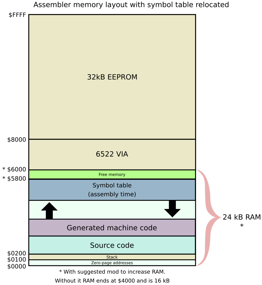
To do this, in the assembler we need two extra lines, right at the start of the source file:
  SYM $5800     ; symbols are to be placed at $5800 (growing downwards)
  ORG $5800     ; code is to be placed at $5800 (growing upwards)
If you haven’t installed my RAM extending mod, change the address from $5800 to $3800, as RAM ends at $4000 in that case.
Now when you assemble your code the output goes to $5800 and is not affected by the symbol table growing, or the later loading of Pascal source.
Meanwhile, in your Pascal code you need to do a similar thing:
{%S $5800 }That ensures that the Pascal compiler symbol table also starts lower in memory, thus not clobbering the generated machine code. That directive also relocates the run-time stack to the same address.
  SYM $5800     ; symbols are to be placed at $5800 (growing downwards)
  ORG $5800     ; code is to be placed at $5800 (growing upwards)

; interface routines in the EEPROM

      jmp begin   ; skip the message
hello asciiz "Hello, world!\n"
begin = *
      lda #<hello
      ldx #>hello
      jsr print
      rts
Load and assemble (LOAD then ASS) the above assembler code, which relocates itself to $5800 and with the symbol table moved to $5800 to avoid a clash with the symbols.
You can test that on its own now by typing RUN. The runtime system automatically starts running at the first emitted object code. In this case, that is the “jmp start” instruction.
  { Relocate symbol table and runtime stack: } {%s $5800}
  { Note: hello_world_relocated.asm should be loaded and compiled before running this }

begin
  writeln ("About to call machine code ...");
  call ($5800);
  writeln ("Machine code done.")
end .
Now load, compile and run the above Pascal code. It will display a message, then call the assembler code at $5800, and then return to display its final message.
If you don’t have the extended RAM mod then change $5800 in the above examples to $3800.
Some useful “exposed” function addresses, plus some zero-page addresses, are pre-loaded into the symbol table (there are around 80 of them, taking around 1630 bytes of RAM in the process). This lets you call various subroutines, like PRINT for outputting to the terminal, DIGITALREAD, DIGITALWRITE, PINMODE and so on, without having to work out where they are in the EEPROM.
If you are desperately short of RAM, and want to avoid these being loaded into the symbol table by the assembler, you could recompile the source, omitting or commenting-out some or all of those in assembler.inc. Look for assembler_library_functions_table. Leave the table there, but omit some or all of the contents.
A list of them is with explanations here.
Example of using the inbuilt functions to multiply two numbers and display the result:
;
;  put 47302 into value
;
  lda #<47302
  sta value
  lda #>47302
  sta value+1
  stz value+2
;
;  put 55 into value2
;
  lda #<55
  sta value2
  lda #>55
  sta value2+1
  stz value2+2
;
;  multiply them to get the result 2601610
;  exp_multiply multiplies value by value2 and puts the result in value
;
  jsr exp_multiply
;
;  display the result (displays value)
;
  jsr display_in_decimal
; done!
rtsThere are three utility functions in the EEPROM code to control the 16 pins on the VIA chip, which operate similarly to the ones on the Arduino.
The functions are in the exposed functions list.
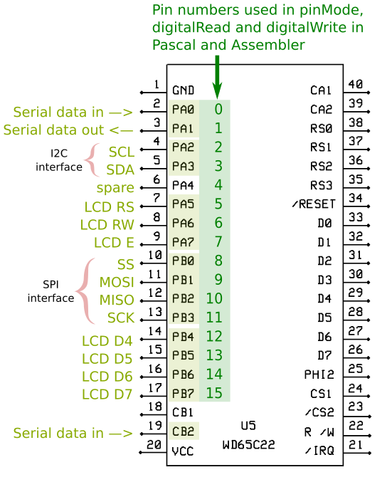
The VIA ports are PA0 to PA7 (pins 2 to 9 on the chip) and PB0 to PB7 (pins 10 to 17 on the chip). For the purposes of these functions they are numbered 0 to 15, where 0 is PA0, 1 is PA1, 8 is PB0 and 15 is PB7, and so on for the ones in-between.
Pins PA0 and PA1 on the VIA are used for the serial interface, as well as CB2 to detect the start bit for incoming serial data.
Pins PA5, PA6, PA7, PB4, PB5, PB6, PB7 are used for the LCD interface.
That leaves 7 pins for your own use (PA2, PA3, PA4, PB0, PB1, PB2, PB3).
pinmode (port, mode). This sets the mode of the port, where 0 is input and 1 is output.
Port in A, mode in X, then jsr pinmode
digitalWrite (port, value). Writes to the specified port. The value can be 0 or 1.
Port in A, value in X, then jsr digitalwrite
digitalRead (port). Reads a value from the specified port. Returns 0 or 1.
Port in A, then jsr digitalread. Returns the value in A.
Example:
;
;  digitalWrite example
;
  jmp begin     ; skip the variable declarations

counter   dfb 0     ; how many toggles we did
pin_state dfb 0     ; current pin state

ITERATIONS = 20     ; how many times to loop (this will be 10 flashes)

begin:

  stz pin_state
  stz counter

;
;  set PA2 to output
;
  lda #2   ; Port PA2
  ldx #1   ; write mode
  jsr pinmode


write_loop:
;
;  write to PA2
;
  lda pin_state
  eor #1   ; toggle state
  sta pin_state
  tax
  lda #2   ; Port PA2
  jsr digitalwrite
;
;  delay 500 ms
;
  ldx #<500
  ldy #>500
  jsr delay
;
;  do it ITERATIONS times
;
  inc counter
  lda counter
  cmp #ITERATIONS
  bcc write_loop
;
;  all done
;
rtsThere are support functions for interfacing with I2C devices, such as real-time clocks, port expanders, and many other peripherals, with the board acting as an I2C master. See I2C support for more details.
There are also support functions for interfacing with SPI devices, such as 7-segment displays, 8x8 matrix displays, port expanders, and many other peripherals, with the board acting as an SPI master. See SPI support for more details.
Debugging assembler code can be a pain — I know from experience. Below are a few suggestions.
When running assembler code the stack pointer is changed to $CF rather than $FF. In other words, the top of the stack is address $1CF. This is so that, if you hit a breakpoint and use various commands like MEM, POKE and so on, the use of the stack in the Editor does not corrupt your user stack. This will reduce your available stack size by 48 bytes (out of 256). That still allows 208 nested subroutine calls, assuming you don’t also push stuff onto the stack, which should be plenty. If it isn’t, in your code you can change the stack pointer, however then the stack “backtrace” shown when you hit a BRK will not be correct.
You can use a handful of instructions to toggle one of the VIA pins, like this:
VIA_PORTA  = $7FF1
DEBUG_MASK = %00010000

  pha
  lda #DEBUG_MASK     ; toggle debug flag
  tsb VIA_PORTA       ; turn it on
  trb VIA_PORTA       ; turn it off
  pla
The VIA pins are set to output by default in the hardware initialisation routines (to avoid floating inputs to the chip).
This toggling is very fast, you would not see it with the naked eye. An oscilloscope or logic analyser could show if that port was toggled. Alternatively leave it on (omit the “trb” instruction) and then you could see if a particular code path had been traversed.
Another technique is to put BRK instructions into your code. The processor actually advances two bytes after a breakpoint, so the byte after BRK is reserved for a breakpoint number. Thus, if you are uncertain if your code has reached a particular spot you can put a BRK there, followed by a breakpoint number, e.g.
   BRK
   DFB 1    ; breakpoint #1
Now if that gets executed you will see something like this:
BRK executed at address $9969, A = $00, X = $01, Y = $01, P = $32, S = $f4, id = $01
Stack: 8c 9b 42 9b 5f 97
The breakpoint processing displays the address of the BRK, followed by the A, X, Y registers, followed by the processor flags (P) and the stack pointer (S). Also the byte after the break is shown as the break “ID”.
Then it displays the stack from S+6 onwards. This is because the processor takes 3 bytes of stack to handle the BRK, plus the breakpoint handler pushes A and X onto the stack before saving the stack register. Finally, the stack register points at the first unused spot, not the last used spot. Thus the bytes shown should be what was on the stack when the break occurred. Assuming for a moment that you haven’t (in your code) pushed registers onto the stack, then you should see a stack “traceback” being the last few JSR addresses.
Be aware that the JSR pushes the program counter + 2 onto the stack (not + 3). Thus you need to add one to each address to see what the address after the JSR was (or subtract 2 to find the address of the JSR itself). So in the example above, the stack traceback was (from earliest to latest):
Remember that the high-order byte is pushed first by the JSR so you have to read the bytes from right to left. Thus “5F 97” becomes $975F, and then adding one gives you $9760.
From the above we conclude that, in this case, a JSR at $975D called something (you can find what by looking at your listing), and then a JSR at $9B40 called something, and finally a JSR at $9B8A called something. Then the BRK was reached.
You could sprinkle multiple BRK instructions through your code to confirm or deny that certain parts of code are executed each with their own unique breakpoint “ID” so you can see which one was reached (without having to match the breakpoint address to the generated code address).
If you do not put an “ID” byte after the BRK, then the code shown will simply be the opcode of the next instruction in the source. If you are planning to do a RESUME then you must put an “ID” byte after each BRK. You could insert breakpoints in places where you want to check the contents of various registers, or other memory locations, and then type RESUME afterwards to move onto the next breakpoint.
You can resume execution after hitting a breakpoint, see below.
After hitting a breakpoint, you can type RESUME to continue at the next instruction. In this case you must put a breakpoint identifier after the breakpoint, or the code will be resumed one byte from the correct place. This means you can put various breakpoints in your code and check that registers (and other memory addresses) are what you expect before resuming execution.
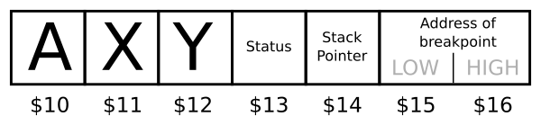
The processor registers are loaded with the values saved when the BRK was executed. These values are saved in the following memory locations:
Another technique is to put “debugging prints” inside your code. This could be used instead of inserting BRK instructions if you just want a breadcrumb trail of what is being executed and in what order. For example:
;
;  Debug point: A is point code
;

debug_message asciiz "Debug point "

debug_point:
  phx
  phy
  pha
  lda #<debug_message
  ldx #>debug_message
  jsr print
  pla
  jsr COUT    ; output the point code
  jsr CROUT   ; newline
  ply
  plx
  rts
Now in your code you could do something like this:
  pha             ; save A
  lda #'A'        ; debug point A
  jsr debug_point ; display message
pla ; retrieve AYou can use the MEMORY command to view any range of memory. For example, to look at the zero-page registers:
: mem $0 $1f
$0000: d3 c7 00 da c9 00 00 00 00 ff ff ff ff 00 00 00  . . . . . . . . . . . . . . . .
$0010: 00 00 00 00 00 00 00 37 c6 00 00 00 00 00 00 00  . . . . . . . 7 . . . . . . . .
Press Ctrl+C to abort a long listing. Values in the range 0x20 to 0x7F are shown in ASCII on the right of the hex numbers. Other values are shown as a period.
For debugging purposes you can use “POKE” to alter any memory address. There is no checking if you are altering a sane memory location.
For example:
POKE $1000 $12 $34 'A'That would put $12 into address $1000, $34 into address $1001, and $41 into address $1002.
You will get a message, and poking will cease, if the value read back from that location is not the value you are attempting to place there. This would happen if you were writing to read-only memory.
You can poke one or more locations (sequentially). The maximum number depends on what will fit into the editor’s command-line buffer which is 256 bytes long including the trailing newline and 0x00 byte.
A possible use of POKE would be to insert extra breakpoints “on the fly” while you are debugging. For example, once you hit one breakpoint (which you put in the code), you may be curious to know what the registers have in them a few instructions later. Referring to your listing for guidance about where to insert your breakpoints you could:
You could also use POKE to remove instructions by replacing them with a NOP instruction ($EA).
You can call any subroutine by using “JSR” in the shell. eg.
JSR $1234Prior to executing the JSR, the shell loads the processor registers from zero-page memory as follows:
You could use POKE to seed those registers.
After the subroutine returns, those four locations will have the new values of those registers placed in them.
You can jump to any address by using “JMP” in the shell. eg.
JMP $1234Prior to executing the JMP, the shell loads the processor registers from zero-page memory as follows:
You could use POKE to seed those registers.
Information and images on this site are licensed under the Creative Commons Attribution 3.0 Australia License unless stated otherwise.