Author: Nick Gammon
Date written: March 2022
The firmware on the EEPROM supports connecting to I2C devices as a master. This is implemented in software and does not require any additional hardware apart from two 4.7k pull-up resistors.
Demonstration video on Vimeo
See:
The Two-Wire interface is extremely useful for connecting multiple devices, as they can all share the same two pins (plus a ground return). This is because the devices are “addressable”. Each device needs to have a unique address in the range 8 to 119. Address 0 is reserved as a “broadcast” address, addresses 1 to 7 are reserved for other purposes, and addresses 120 to 127 are reserved for future use.
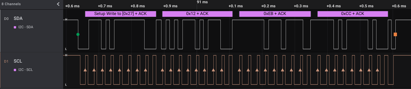
Screen capture of the logic analyzer while sending data to the MCP23017 chip (open image in new tab for more detail).
I2C uses an “open drain” system, which allows multiple devices to be connected to the SCL/SDA lines without any danger of them “fighting” over who sets the bus low or high. Devices (including the master) only ever drive the lines low (by setting the port to output and writing a zero). To send a 1-bit they set the port to high-impedence (input) and let the pull-up resistors pull the line high. This is why the pull-up resistors are required, without them the lines would never go high and the system would hang.
Multiple devices may be connected simultaneously by simply connecting SDA and SCL together for each device. Only one set of pull-up resistors are required, you don’t need one pair for each device.
The code expects you to connect:
You can change that configuration by altering the code (i2c.inc) and re-assembling it.
You need two pull-up resistors (recommended value is 4.7k) on SDA and SCL as shown below.

The above image shows how you might wire up a DS1307 clock chip and a MCP23017 port-expander. You can buy the clock chips on their own very cheaply, or as a pre-assembled board, as I did in my example photo.
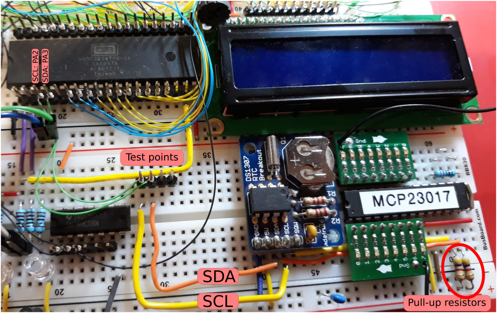
The clock board shown has the pull-up resistors already on it. The photo also shows a MCP23017 I2C port-expander wired onto the same SCL/SDA pins as the clock.
The firmware on the EEPROM has three exposed functions (subroutines) you can call:
This just initialises the I2C interface, basically by putting SCL and SDA into input mode. You can call this once to make sure those two pins are inputs. However the other functions call this anyway, so it is not required, unless you want to ensure that the pins are correctly configured in advance of using I2C.
This is for sending data from the master (you) to the slave (some other chip). You need to:
After the call the carry bit will be set on success and clear on failure.
Example:
  lda #<set_time_message
  sta VALUE
  lda #>set_time_message
  sta VALUE+1
  ldy #8                ; length: register number + 7 data bytes
  lda #CLOCK_PORT       ; DS1307 port
  jsr i2c_send
  bcc i2c_failure


set_time_message:
  dfb $00              ; start setting register zero
  dfb $00,$32,$04      ; second, minute, hour  (4:34:00)
  dfb $02              ; day of week: Tuesday
  dfb $31,$01,$22      ; day / month / year  (31/01/22)

CLOCK_PORT = $68 ; DS1307 is on I2C port 0x68This is for receiving data from the slave (some other chip) to the master (you). You need to:
After the call the carry bit will be set on success and clear on failure.
Example:
  lda #<read_time_work
  sta VALUE
  lda #>read_time_work
  sta VALUE+1
  ldy #7                    ; read 7 bytes
  lda #CLOCK_PORT           ; DS1307 port
  jsr i2c_receive
  bcc i2c_failure

read_time_work BLK 7               ; 7-byte workarea for reading time

CLOCK_PORT = $68 ; DS1307 is on I2C port 0x68Information and images on this site are licensed under the Creative Commons Attribution 3.0 Australia License unless stated otherwise.