
Author: Nick Gammon (written in 2022)
In order to “talk” to Ben’s 6502 Board you need some way of interfacing a keyboard and monitor. You could conceivably use a “dumb terminal” but they may be hard to find these days. The simplest thing is to obtain a FTDI cable, available from eBay for around $US 10.
One end plugs into a USB port on your PC/Mac/Linux box, and the other end breaks out the six RS232 signals:

The order shown in the photos is from “above” the connector, in other words you cannot see the metal pins inside the connector (they are visible on the “bottom” side).
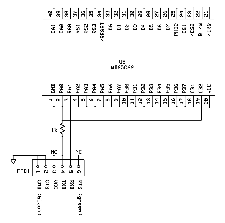
In order for the code to detect the start of a byte, we need to generate an interrupt on the falling edge of the received data. Thus also:

I found miniterm very good on my Linux box. It appears to be available from https://pyserial.readthedocs.io/en/latest/index.html.
Miniterm is available on Mac, Windows and Linux. See https://pypi.org/project/pyserial/#files
It requires Python 3.x to run. You may need to install that as well.
When I was testing G-Pascal I used this command:
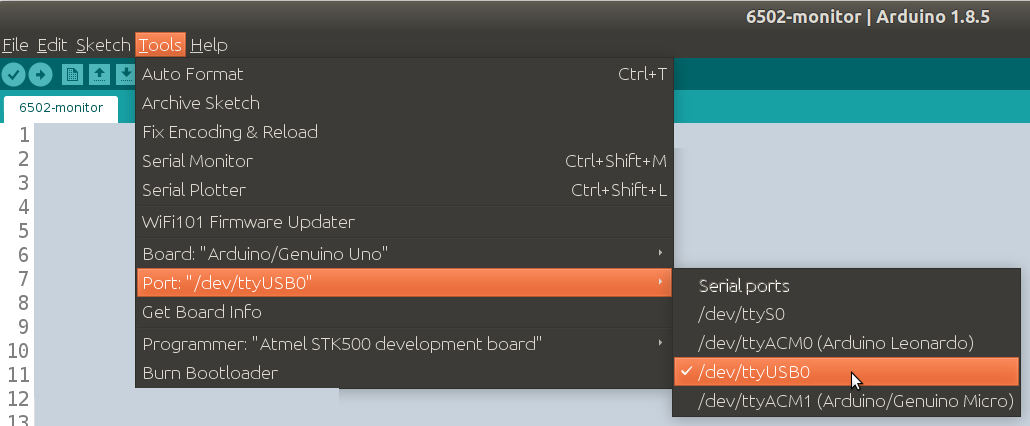
miniterm /dev/ttyUSB0 4800 -eThe port (in my case “/dev/ttyUSB0”) may be different. If you aren’t sure what it is, try opening the Arduino IDE and looking at the Tools Menu -> Port, like this:
The “-e” command-line option on Miniterm activates “local echo”. You need this because the board will not echo back what you type (and if it did, it would be corrupted as described above).
Type Ctrl+] to exit from Miniterm.
Whilst you can use a dumb terminal that has a RS232 interface, you need to be aware the the electrical signals are not compatible with the 6502 processor. The original RS232 specs had a “1” bit as -12V and a “0” bit as +12V. You would need to use a conversion cable, or make up something, for example with the MAX232 chip, which will do the conversion.
The way Ben described the address decoding for the EEPROM, it is possible for both the CPU and the EEPROM to be attempting to write to the bus at the same time (eg. STA $8000). The suggested wiring uses a spare NAND gate on the existing board to prevent that. This would prevent possible damage to the CPU and/or the EEPROM if such code was attempted.
I suggest using the spare NAND gate on U4 and run R/W from the CPU through the AND gate to invert it, and run that to /OE on the EEPROM.

I am using the 74LS00 as an inverter here, and you can see that when the CPU is writing, then the output of the EEPROM is disabled.
It helps to recover from runaway or rogue code by pressing a switch button connected to the NMI pin of the 65C02. This does a “warm restart” which basically starts the code again, however it retains your existing source code.

The way Ben did his address decoding for the RAM meant that only 16k of the chip’s 32k was available. You can make a simple change using a 74LS08 “AND” gate that extends the RAM address space to 0x6000 rather than 0x4000, thus giving you 24k of RAM (an extra 8k) for the cost of a one dollar chip and a few jumper cables. This change is required to compile the “Adventure” game because of its size.

This increases the top of RAM from $3FFF to $5FFF. Basically if both A13 and A14 are high then the RAM output enable will be off. In other words, the RAM is disabled when both the 0x4000 and 0x2000 address bits are set (because we are “and”ing them together), which means that the RAM works up to 0x6000 rather than 0x4000 as it originally did.