This page can be quickly reached from the link: http://www.gammon.com.au/bootloader
This sketch was inspired by the Optiloader sketch written for the Arduino. However it is a total rewrite, in order to accomodate the Mega2560 board, which the original one did not handle, due to the larger address space.
Supported bootloaders
The code for the following bootloaders is incorporated in the sketch, and will be downloaded depending on which signature is detected:
- Atmega8 (1024 bytes)
- Atmega168 Optiboot (512 bytes)
- Atmega328 Optiboot (for Uno etc. at 16 MHz) (512 bytes)
- Atmega328 (8 MHz) for Lilypad etc. (2048 bytes)
- Atmega32U4 for Leonardo (4096 bytes)
- Atmega1280 Optiboot (1024 bytes)
- Atmega1284 Optiboot (1024 bytes)
- Atmega2560 with fixes for watchdog timer problem (8192 bytes)
- Atmega16U2 - the bootloader on the USB interface chip of the Uno
- Atmega256RFR2 - the bootloader on the Pinoccio Scout board
You have the option of programming (writing) the bootloader or verifying (checking) the existing bootloader.
[EDIT] Changed on 26 November 2014 to allow you to optionally omit some of the above bootloaders to save space in the programming board (eg. for the Arduino Micro).
Code
Source on GitHub
The latest version will be available on GitHub:
https://github.com/nickgammon/arduino_sketches
You can see from that what recent changes were.
This particular sketch is in the "Atmega_Board_Programmer" subdirectory.
Decoupling capacitors
Tip
If you are programming your own board, or using a breadboard, then decoupling capacitors are required! Decoupling capacitors are typically ceramic capacitors, 0.1 µF (100 nF) between Vcc and Gnd (and also AVcc and Gnd if applicable), close to the chip.
If you don't use them you may find that the chip is recognized, but cannot be programmed. They are not an optional extra.
If you are just programming one Arduino board from another, then they will already have decoupling capacitors on the board, so you don't need to worry about them.
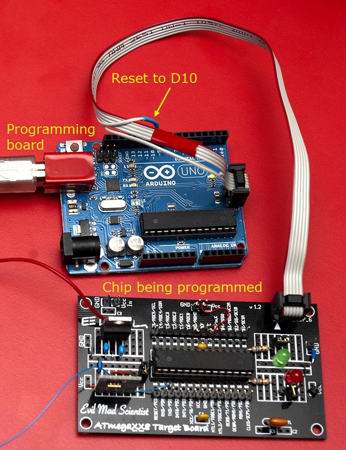
Programming cable
For boards which have an ICSP header, it helps to make up a programming cable (although not essential). You can do this by getting a 6-pin IDC cable, and cutting the 5th wire out of circuit and soldering a pin onto it, like this:

This wire (the reset signal) gets plugged into D10 on the Arduino with the programming sketch on it, as in the images below.
If you don't have such a cable, just connect together the pins as described below.
Programming a board
Upload above sketch to the "programming" Uno. Connect programming cable as shown.
Wiring for Uno and similar

(Ruggeduino depicted with programming cable)

(Uno depicted with "manual" programming cable)
Arduino Uno      Target Uno

D10 (SS)            Reset
D11 (MOSI)          D11
D12 (MISO)          D12
D13 (SCK)           D13

Gnd                 Gnd
+5V                 +5V
Example output for Uno
Atmega chip programmer.
Written by Nick Gammon.
Entered programming mode OK.
Signature = 0x1E 0x95 0x0F
Processor = ATmega328P
Flash memory size = 32768 bytes.
LFuse = 0xFF
HFuse = 0xDE
EFuse = 0xFD
Lock byte = 0xCF
Bootloader address = 0x7E00
Bootloader length = 512 bytes.
Type 'G' to program the chip with the bootloader ...
Once you see the above, type "G" into the serial monitor to commence programming ...
Erasing chip ...
Writing bootloader ...
Committing page starting at 0x7E00
Committing page starting at 0x7E80
Committing page starting at 0x7F00
Committing page starting at 0x7F80
Written.
Verifying ...
No errors found.
Writing fuses ...
LFuse = 0xFF
HFuse = 0xDE
EFuse = 0xFD
Lock byte = 0xCF
Done.
Type 'C' when ready to continue with another chip ...
This takes one second.
[EDIT] The more recent versions of the sketch ask this question:
Type 'L' to use Lilypad (8 MHz) loader, or 'U' for Uno (16 MHz) loader ...
Type "U" if you are using a Uno (or any board running at 16 MHz) or "L" if you are using an 8 MHz board.
[EDIT] (23 December 2013) Sketch version 1.21 onwards automatically clears the "divide clock by 8" fuse bit before programming.
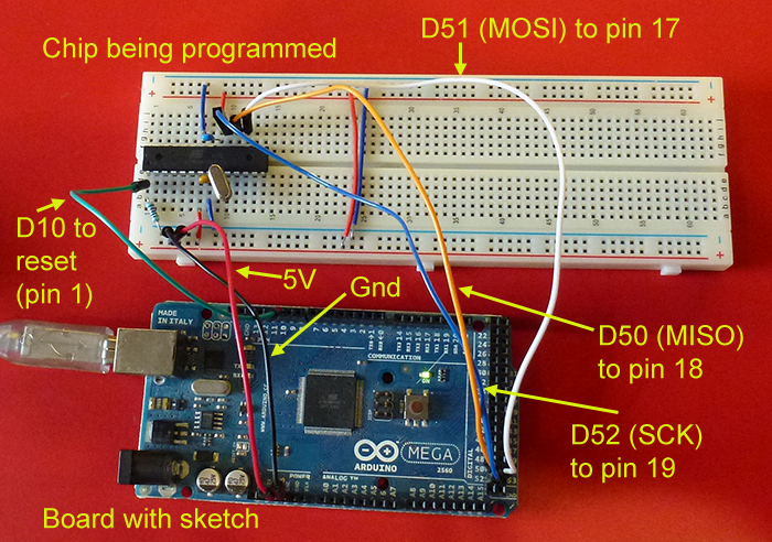
Wiring for Mega2560 and similar

Arduino Uno      Target Mega2560

D10 (SS)            Reset
D11 (MOSI)          D51
D12 (MISO)          D50
D13 (SCK)           D52

Gnd                 Gnd
+5V                 +5V
Example output for Mega2560
Atmega chip programmer.
Written by Nick Gammon.
Entered programming mode OK.
Signature = 0x1E 0x98 0x01
Processor = ATmega2560
Flash memory size = 262144 bytes.
LFuse = 0xFF
HFuse = 0xD8
EFuse = 0xFD
Lock byte = 0xCF
Bootloader address = 0x3E000
Bootloader length = 8192 bytes.
Type 'G' to program the chip with the bootloader ...
Once you see the above, type "G" into the serial monitor to commence programming ...
Erasing chip ...
Writing bootloader ...
Committing page starting at 0x3E000
Committing page starting at 0x3E100
Committing page starting at 0x3E200
Committing page starting at 0x3E300
Committing page starting at 0x3E400
Committing page starting at 0x3E500
Committing page starting at 0x3E600
Committing page starting at 0x3E700
Committing page starting at 0x3E800
Committing page starting at 0x3E900
Committing page starting at 0x3EA00
Committing page starting at 0x3EB00
Committing page starting at 0x3EC00
Committing page starting at 0x3ED00
Committing page starting at 0x3EE00
Committing page starting at 0x3EF00
Committing page starting at 0x3F000
Committing page starting at 0x3F100
Committing page starting at 0x3F200
Committing page starting at 0x3F300
Committing page starting at 0x3F400
Committing page starting at 0x3F500
Committing page starting at 0x3F600
Committing page starting at 0x3F700
Committing page starting at 0x3F800
Committing page starting at 0x3F900
Committing page starting at 0x3FA00
Committing page starting at 0x3FB00
Committing page starting at 0x3FC00
Committing page starting at 0x3FD00
Committing page starting at 0x3FE00
Committing page starting at 0x3FF00
Written.
Verifying ...
No errors found.
Writing fuses ...
LFuse = 0xFF
HFuse = 0xD8
EFuse = 0xFD
Lock byte = 0xCF
Done.
Type 'C' when ready to continue with another chip ...
This takes three seconds.
Programming a "bare bones" board
Atmega chip programmer.
Written by Nick Gammon.
Entered programming mode OK.
Signature = 0x1E 0x95 0x0F
Processor = ATmega328P
Flash memory size = 32768 bytes.
LFuse = 0xFF
HFuse = 0xDA
EFuse = 0xFC
Lock byte = 0xFF
Bootloader address = 0x7E00
Bootloader length = 512 bytes.
Type 'G' to program the chip with the bootloader ...
Erasing chip ...
Writing bootloader ...
Committing page starting at 0x7E00
Committing page starting at 0x7E80
Committing page starting at 0x7F00
Committing page starting at 0x7F80
Written.
Verifying ...
No errors found.
Writing fuses ...
LFuse = 0xFF
HFuse = 0xDE
EFuse = 0xFD
Lock byte = 0xCF
Done.
Type 'C' when ready to continue with another chip ...
Note that the fuses were changed after the board was programmed.
Programming a RBB (really bare bones board)

Atmega chip programmer.
Written by Nick Gammon.
Entered programming mode OK.
Signature = 0x1E 0x95 0x0F
Processor = ATmega328P
Flash memory size = 32768 bytes.
LFuse = 0xFF
HFuse = 0xDA
EFuse = 0xFD
Lock byte = 0xCF
Bootloader address = 0x7E00
Bootloader length = 512 bytes.
Type 'G' to program the chip with the bootloader ...
Erasing chip ...
Writing bootloader ...
Committing page starting at 0x7E00
Committing page starting at 0x7E80
Committing page starting at 0x7F00
Committing page starting at 0x7F80
Written.
Verifying ...
No errors found.
Writing fuses ...
LFuse = 0xFF
HFuse = 0xDE
EFuse = 0xFD
Lock byte = 0xCF
Done.
Type 'C' when ready to continue with another chip ...
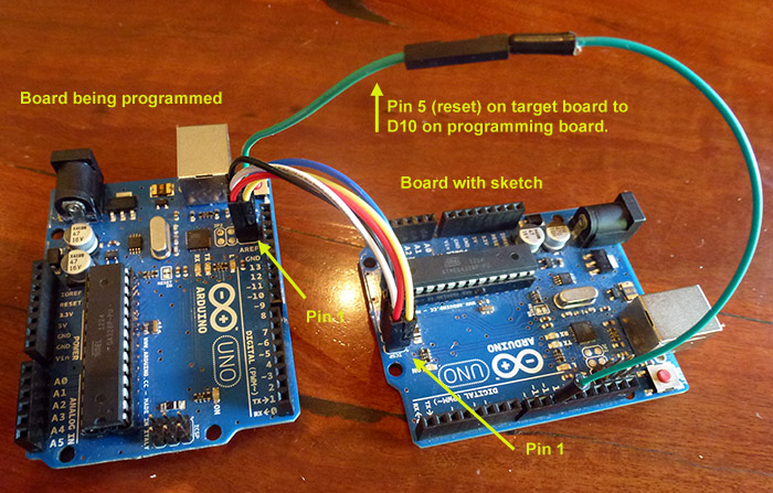
Wiring for Leonardo
The Leonardo does not expose the ICSP pins on the board "header" pins so you either have to use the IDC programming cable described earlier, or connect the ICSP pins of both boards together using female-to-female hookup wire, like this:

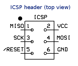
You connect pin 1 of the ICSP header (the one with the dot) on one board to pin 1 on the other board. And connect pin 2 of each board together, and so on, omitting pin 5 which is Reset.
Reset on the Leonardo is connected to Pin 10 of the programming board, as shown.
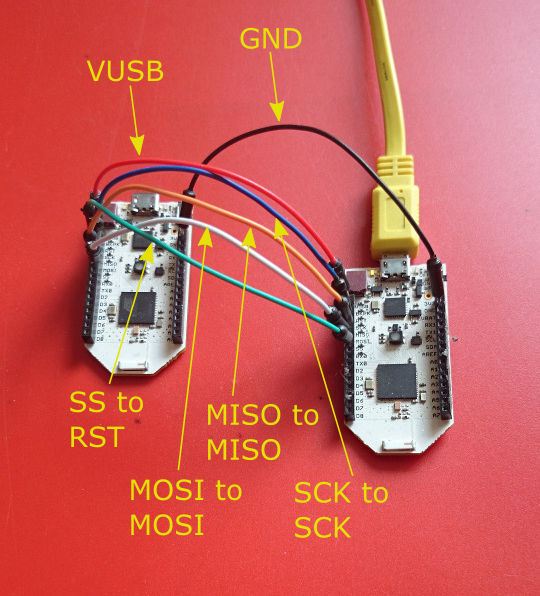
Close-up of the wiring:

Pay attention to the pin numbers if you have the boards end-to-end because pin 1 on one board is not adjacent to pin 1 on the other board (because they are turned 180°).
You can use one Leonardo to program another Leonardo (or a Uno) providing you use this wiring method - use the ICSP headers as shown and connect them as shown.
Top-down view of the ICSP header. Notice the dot (which is printed on the board next to pin 1).
Adding other bootloaders
In order to convert the .hex bootloader files on disk for use with this sketch I ran this Lua script:
--[[
  Do MD5 sumcheck of Arduino bootloader .hex file
  Nick Gammon
  5 May 2012
  Amended 10 October 2014, to get PROGMEM line right for IDE 1.5.8

  To use:

  1. Download MUSHclient from: http://www.gammon.com.au/downloads/dlmushclient.htm
     MUSHclient is free and open source.
     Source code at: https://github.com/nickgammon/mushclient
     You are not required to enter any personal information to obtain the download.

  2. Install MUSHclient (requires Windows, or Wine on Linx and OS/X)

  3. Run MUSHclient (click past all the introductory screens)

  4. Make a "new world" in MUSHclient (File menu -> New World)

  5. Fill in the fields:
     World name:     Arduino  (doesn't really matter what it is)
     TCP/IP address: 0.0.0.0
     Port:           4000     (doesn't really matter what it is)

  6. A window will open with various messages about the version number, etc.

  7. Open an Immediate scripting window (Game menu -> Immediate).
     Pressing Ctrl+I is a shortcut for this.

  8. Copy this script and paste it into the Immediate window (RH-click to do this)

  9. Click the Run button.

 10. Navigate to the bootloader .hex file that you want to process.

 11. Click "Open".

 12. Assuming no errors, close the Immediate window.

 13. In the output window you should see a whole lot of hex codes.

 14. Scroll back to the line of hyphens, and copy from the line below that, eg.
     ------------------------------------------------------------
     // File =  Arduino-COMBINED-dfu-usbserial-atmega16u2-Uno-Rev3.hex
     // Loader start: 3000, length: 4096
     // MD5 sum = D8 8C 70 6D FE 1F DC 38 82 1E CE AE 23 B2 E6 E7
     const byte Arduino_COMBINED_dfu_usbserial_atmega16u2_Uno_Rev3_hex [] PROGMEM = {
      0x4B, 0xC0, 0x00, 0x00, 0x64, 0xC0, 0x00, 0x00, 0x62, 0xC0, 0x00, 0x00, 0x60, 0xC0, 0x00, 0x00,
     ...
     }; // end of <whatever your file name was>

  That stuff is your bootloader as an array of bytes.

--]]


require "getlines"

loader = nil
adder = 0

-- given a start address, deduce where the bootloader ends
end_addresses = {
  [0x1000] = 0x2000,
  [0x1C00] = 0x2000,
  [0x1D00] = 0x2000,
  [0x1E00] = 0x2000,
  [0x3000] = 0x4000,
  [0x3800] = 0x4000,
  [0x3E00] = 0x4000,
  [0x7000] = 0x8000,
  [0x7800] = 0x8000,
  [0x7E00] = 0x8000,
  [0xF800] = 0x10000,
  [0x1F000] = 0x20000,
  [0x1FC00] = 0x20000,
  [0x3E000] = 0x40000,
  }

function process (size, address, rectype, data)

  size = tonumber (size, 16)
  address = tonumber (address, 16) + adder
  rectype = tonumber (rectype)
  local binarydata = utils.fromhex (data)

  if rectype == 2 then  -- Extended Segment Address Record
    adder = tonumber (data, 16) * 16  -- high order address byte
  elseif rectype == 0 then -- data record
    if loader == nil then
      start_address = address
      end_address = end_addresses [address]
      if end_address == nil then
        ColourNote ("red", "", "Don't know end address for " .. bit.tostring (address, 16))
        ColourNote ("red", "", "Please add to table: end_addresses")
        error "Cannot continue"
      end -- if end address not found

      -- work out loader length
      length = end_address - address
      -- pre-fill with 0xFF in case not every byte supplied
      loader = string.rep ("\255", length)
      print (string.format ("// Loader start: %X, length: %i", address, length))
    end -- no loader yet

    -- insert data over where the 0xFF was
    if address >= start_address and (address + size) <= end_address then
      loader = loader:sub (1, address - start_address) ..
               binarydata ..
               loader:sub (address - start_address + size + 1, length)
    else
      ColourNote ("red", "", "Address " .. bit.tostring (address, 16) .. " out of expected range.")
    end  -- if in range
  end -- if

end -- function process

print (string.rep ("-", 60))

-- get bootloader file
filename = utils.filepicker ("Choose a bootloader", nil, "hex", { hex = "Hex files" })

-- none chosen, give up
if not filename then return end

-- show file
local fn = string.match (filename, "\\([^\\]+)$")
print ("// File = ", fn)

-- process each line
for line in io.lines (filename) do
  size, address, rectype, data = string.match (line, "^:(%x%x)(%x%x%x%x)(%x%x)(%x+)%s*$")
  if size then
    process (size, address, rectype, data:sub (1, -3))
  else
    ColourNote ("red", "", "Discarded line: " .. line)
  end -- if
end -- for loop

--print (utils.tohex (loader))

-- sumcheck it
Tell ("// MD5 sum = ")
md5sum = utils.tohex (utils.md5 (loader))
print ((string.gsub (md5sum, "(%x%x)", "%1 ")))

print ""

--     show bootloader in hex

-- convert into C array
print (string.format ("const byte %s [] PROGMEM = {",
       string.gsub (fn, "[^%a%d]", "_")))
for i = 1, #loader do
  Tell (string.format ("0x%02X, ", loader:sub (i, i):byte ()))
  if (i - 1) % 16 == 15 then print "" end
end -- of for each byte
print (string.format ("}; // end of %s", string.gsub (fn, "[^%a%d]", "_")))
Because it uses a few special features (like a file picker, MD5 sum calculator etc.) you need to run this from within MUSHclient ... a MUD game client available for free download from this site.
Just download MUSHclient (see the downloads page) and install. Then make a "dummy" world file (File menu -> New World) and type in "Arduino" as the world name and "0.0.0.0" as the TCP/IP address, as shown:

Close the world configuration, and then type Ctrl+I to open the Immediate programming window (Game menu -> Immediate) and paste the above script into it, then hit Run, as shown:

A file-picker will open, you can navigate to the bootloader .hex file that you want to process, and then (all being well) the appropriate hex codes will be shown in the main window. Close the Immediate window, and then just copy and paste into your bootloader sketch (make a separate xxxx.h tab like I did for the other bootloaders).
You will then need to fill in the appropriate figures into the signatures table, such as the bootloader start address, size, programming page size (see the datasheet) and the correct fuse and lock bits. The fuse bytes will probably be the ones mentioned in the boards.txt file in the Arduino environment, for the chip in question.
The above script is now part of the download from GitHub in the file named: bootloader_converter.lua
Checking what bootloader is installed
The thread below describes a sketch that does a MD5 sumcheck of your bootloader, so you can see what bootloader you have installed:
http://www.gammon.com.au/forum/?id=11633
Alternate clock source
As an alternative to a crystal or resonator, the sketch also outputs an 8 MHz clock on pin D9 of the programming board (using Timer 1). Thus you just need to connect D9 on the programming board to XTAL1 of the target board and this will provide a clock signal, enabling this sketch to run.
Atmega1280
Updated on 9 September 2013 to use the Optiboot loader for the Atmega1280. This is smaller and avoids certain issues like the inability to upload a sketch with "!!!" in it.
However please note that if you burn a bootloader for the 1280 chip you need to add this to the end of the boards.txt in the Arduino distribution folder:
##############################################################

megao.name=Arduino Mega1280 Optiboot
megao.upload.protocol=arduino
megao.upload.maximum_size=130048
megao.upload.speed=115200
megao.bootloader.low_fuses=0xff
megao.bootloader.high_fuses=0xdc
megao.bootloader.extended_fuses=0xf5
megao.bootloader.path=optiboot
megao.bootloader.file=optiboot_atmega1280.hex
megao.bootloader.unlock_bits=0x3F
megao.bootloader.lock_bits=0x0F
megao.build.mcu=atmega1280
megao.build.f_cpu=16000000L
megao.build.core=arduino
megao.build.variant=mega
In my case the file was in:
/Applications/Arduino_1.0.5.app/Contents/Resources/Java/hardware/arduino/boards.txt
However you would need to find where it is in your distribution.